Typical System Arrangements
Basic System Arrangements Examples
Countless applications are possible with Power Team hydraulic components. For presses, lifting, jacking applications, production or maintenance setups. The system arrangements below are a small sample of typical solutions that can be configured.
System Arrangement Considerations:
- What degree of accuracy is needed for the application? (For higher accuracy, recommend PLC Automation controls vs. manual)
- What push or pull tonnage/stroke is required per cylinder in your application? (Consider what accessories or end attachments)
- Does the application require multiple cylinders? (Consider how these will be connected or plumbed in a circuit)
Is the application stationary, or must the components be light in weight for easy portability? (Steel vs. Aluminum materials) - Do you need to extend a rod or cable through the center of the cylinder for the application, as in a tensioning operation?
- Does the application require that the cylinder fit within limited-clearance work areas? (Review cylinder stupefactions)
- Will the cylinder need to withstand off-center loads? (Consider Double Acting or swivel load caps to maintain loading)
- Does the application require that the lifted load be supported for extended periods of time? (Consider locking collars are ideal for such jobs, as are cribbing blocks)
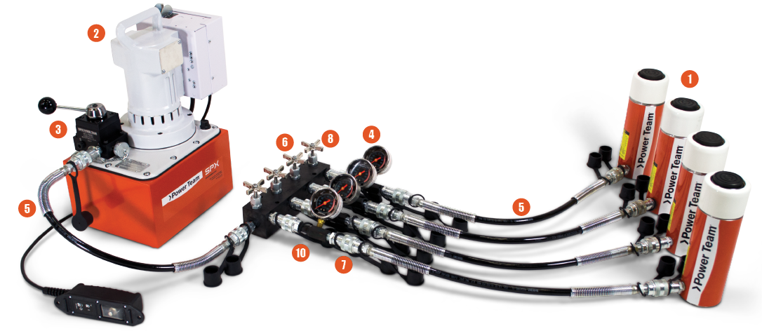
Four Point System (Electric Pump) with Four Port Manifold Block with Controls and Gauges
Component Identification Key:
- Cylinder/Jack/Tool – applies hydraulic force.
- Pump – a device for converting mechanical energy to fluid energy.
Directional valve – controls the direction of hydraulic fluid in the system. - Gauge – measures P.S.I. pressure (Pounds per Square Inch) and/or Force.
- Hose – transports hydraulic fluid.
Manifold – allows distribution of hydraulic fluid from one source to several cylinders. - Quick Coupling—When separated, “hose half” and “cylinder half” couplings are used for quick connection and fluid flow check.
- Shut-Off Valve – regulates the flow of hydraulic fluid to or from cylinders.
- Load-Lowering Valve – allows metered lowering of the cylinder and provides safety when prolonged load holding is required.
- Shut-Off Valve - this valve regulates the flow of hydraulic fluid to or from cylinders.
- Load-Lowering Valve - allows metered lowering of the cylinder and provides safety when prolonged load holding is required.
- T-Gauge Adapter - allows for pressure/tonnage gauge installation anywhere in the hydraulic system.

Single Point System (Hand Pump) with Flow Control and a Gauge
Component Identification Key:
- Cylinder/Jack/Tool – applies hydraulic force.
- Pump – a device for converting mechanical energy to fluid energy.
Directional valve – controls the direction of hydraulic fluid in the system. - Gauge – measures P.S.I. pressure (Pounds per Square Inch) and/or Force.
- Hose – transports hydraulic fluid.
Manifold – allows distribution of hydraulic fluid from one source to several cylinders. - Quick Coupling—When separated, “hose half” and “cylinder half” couplings are used for quick connection and fluid flow check.
- Shut-Off Valve – regulates the flow of hydraulic fluid to or from cylinders.
- Load-Lowering Valve – allows metered lowering of the cylinder and provides safety when prolonged load holding is required.
- Shut-Off Valve - this valve regulates the flow of hydraulic fluid to or from cylinders.
- Load-Lowering Valve - allows metered lowering of the cylinder and provides safety when prolonged load holding is required.
- T-Gauge Adapter - allows for pressure/tonnage gauge installation anywhere in the hydraulic syste
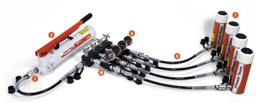
Four Point System (Hand Pump) with Four Port Manifold Block with Controls and Gauges
Component Identification Key:
- Cylinder/Jack/Tool – applies hydraulic force.
- Pump – a device for converting mechanical energy to fluid energy.
Directional valve – controls the direction of hydraulic fluid in the system. - Gauge – measures P.S.I. pressure (Pounds per Square Inch) and/or Force.
- Hose – transports hydraulic fluid.
Manifold – allows distribution of hydraulic fluid from one source to several cylinders. - Quick Coupling—When separated, “hose half” and “cylinder half” couplings are used for quick connection and fluid flow check.
- Shut-Off Valve – regulates the flow of hydraulic fluid to or from cylinders.
- Load-Lowering Valve – allows metered lowering of the cylinder and provides safety when prolonged load holding is required.
- Shut-Off Valve - this valve regulates the flow of hydraulic fluid to or from cylinders.
- Load-Lowering Valve - allows metered lowering of the cylinder and provides safety when prolonged load holding is required.
- T-Gauge Adapter - allows for pressure/tonnage gauge installation anywhere in the hydraulic syste
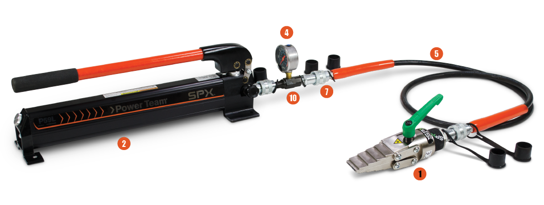
Single Point Tool System (Hand Pump) with Spreader and Gauge
Component Identification Key:
- Cylinder/Jack/Tool – applies hydraulic force.
- Pump – a device for converting mechanical energy to fluid energy.
Directional valve – controls the direction of hydraulic fluid in the system. - Gauge – measures P.S.I. pressure (Pounds per Square Inch) and/or Force.
- Hose – transports hydraulic fluid.
Manifold – allows distribution of hydraulic fluid from one source to several cylinders. - Quick Coupling—When separated, “hose half” and “cylinder half” couplings are used for quick connection and fluid flow check.
- Shut-Off Valve – regulates the flow of hydraulic fluid to or from cylinders.
- Load-Lowering Valve – allows metered lowering of the cylinder and provides safety when prolonged load holding is required.
- Shut-Off Valve - this valve regulates the flow of hydraulic fluid to or from cylinders.
- Load-Lowering Valve - allows metered lowering of the cylinder and provides safety when prolonged load holding is required.
- T-Gauge Adapter - allows for pressure/tonnage gauge installation anywhere in the hydraulic syste

Connect with Our Team
Complete the form and a member of our team will get back to you shortly.
Solution Development
Technical Expertise
Accurate Estimates
On-site Support
Regulatory Guidance
- 1
- 2


